CADKEY spanned three generations of file formats. Gen 1 (1986–1988) used 32-bit floats in a clean layout. Gen 3 (2002+) wrapped ACIS SAB in an OLE2 container — well-documented. Gen 2 (v6–98, 1997–1998) was the gap: 64-bit doubles in a custom binary layout, zero public documentation, abandoned by its vendor after a chain of acquisitions. Twenty-eight sample .prt files from the CADKEY 98 SDK, totaling roughly 10MB of opaque binary.
This is the byte-level format specification that didn’t exist.
Continue with Part 2: The Boundary Between Curves and Faces →
The approach
Dead ends (compressed)
Five abandoned strategies preceded the working solution:
- Wine + CK98. CADKEY 98 launches under Wine. Immediately demands a parallel-port dongle. Twenty-year-old DRM doesn’t resolve itself. Abandoned.
- DOSBox + cadutil.exe. The SDK’s 16-bit batch converter runs inside DOSBox. Produces output. Cannot be programmatically driven from outside the emulator. Shelved.
- Brute-force double scanning. Walking every 8-byte window produced candidate 3D coordinates — and enough noise to make the signal useless without entity structure.
- Footer directory parsing. The
0x0Btail markers looked like offset tables. They weren’t. Structural patterns were inconsistent across files. - AG entity table. SDK documentation references an Advanced Geometry table for NURBS control points. Headers are present. Full parsing deferred — not required for wireframe extraction.
What worked: marker-based scanning
Every Gen 2 PRT file begins with magic bytes A5 0F F0 5A. After the 32-byte header, the file is a heterogeneous database stream — records of different types interleaved in creation order, each prefixed with a 4-byte section marker:
| Marker | Record | Count (toyclip) | Size |
|---|---|---|---|
02 02 00 ff | COEDGE (half-edge) | 630 | 120 B fixed |
02 03 00 ff | Wireframe entities | 177 | Variable |
02 04 00 ff | FACE-like records (subtype 2) | 84 | 220 B fixed |
02 05 00 ff | Piecewise cubic 3D spline coefficients | 38 | 344–2,072 B |
0b 10 0f ff | Plane→entity map | 35 | 16 B fixed |
0b 0a / 0b 0d | Polymorphic tail records | varies | 16 B mappings or 2,092 B blocks |
0b 12 | Render/display data | varies | 15,372 B in toyclip |
A critical early discovery: the file is raw C structs serialized directly to disk. DOS-era compilers aligned struct members to word boundaries — long runs of 00 bytes aren’t null values, they’re padding. The FF FF FF FF sentinels mark end-of-list or no-value. This told us entity types would be enums and geometry would be doubles at predictable offsets.
Entity geometry
Every wireframe entity shares an identical header layout at marker + 20. The full 52-byte header, fully characterized:
| Offset | Size | Field | Value |
|---|---|---|---|
| +0 | 2 | Entity type (u16) | 1–15 |
| +2 | 2 | Reserved | Always 00 01 |
| +4 | 2 | Reserved | Always 00 01 |
| +6 | 2 | Reserved | Always 00 01 |
| +8 | 4 | Reserved | Always 00 00 00 00 |
| +12 | 2 | Level (u16) | 1-based |
| +14 | 2 | Reserved | Always 00 00 |
| +16 | 4 | Previous entity ID (u32) | Doubly-linked list |
| +20 | 4 | Next entity ID (u32) | Doubly-linked list |
| +24 | 4 | Construction plane ID (u32) | Links to COEDGE via 0b_10 map |
| +28 | 4 | Display flag (u32) | FC 00 FF FF standard / FF FF FF FF SPLINE |
| +32 | 4 | Display flag (u32) | E0 FF FF FF standard / FF FF FF FF SPLINE |
| +36 | 4 | Tessellation hint (u32) | 5 or 12 for LINEs, 1 for arcs |
| +40 | 2 | Pen/color (u16) | 66 (0x42) is standard |
| +44 | 4 | Reserved | Always 00 00 00 00 |
| +48 | 4 | Reserved | Always 00 00 00 00 |
Sixteen bytes of the header are constant across every entity in every file — padding and sentinel values the C struct serializer wrote verbatim. The variable fields are entity type, level, linked-list pointers, plane reference, and the three display flags at +28/+32/+36.
Geometry follows at +52 — six little-endian doubles, interpreted per entity type:
| Type | Name | Geometry format | DXF output |
|---|---|---|---|
| 1 | ARC1 | cx,cy,cz,r,sa,sw | ARC |
| 2 | LINE | x₁,y₁,z₁,x₂,y₂,z₂ | LINE |
| 3–14 | ARC/CIRCLE variants | cx,cy,cz,r,sa,sw | ARC/CIRCLE |
| 15 | CONTROL POINT | x,y,?,0,0,0 | Filtered |
The type code identifies the CADKEY creation tool, not the geometry format. Types 1 and 3–14 all share identical (cx,cy,cz,r,sa,sw) storage — ARC1 is construction arc geometry, not a LINE variant. Type 2 is the sole LINE type with 3D world-space endpoints (x₁,y₁,z₁,x₂,y₂,z₂). Two fields long listed as “unknown” (d4 and d5) were Z-coordinates of the LINE endpoints — the format always stored 3D coordinates even for geometry on a 2D construction plane.

Construction plane filtering
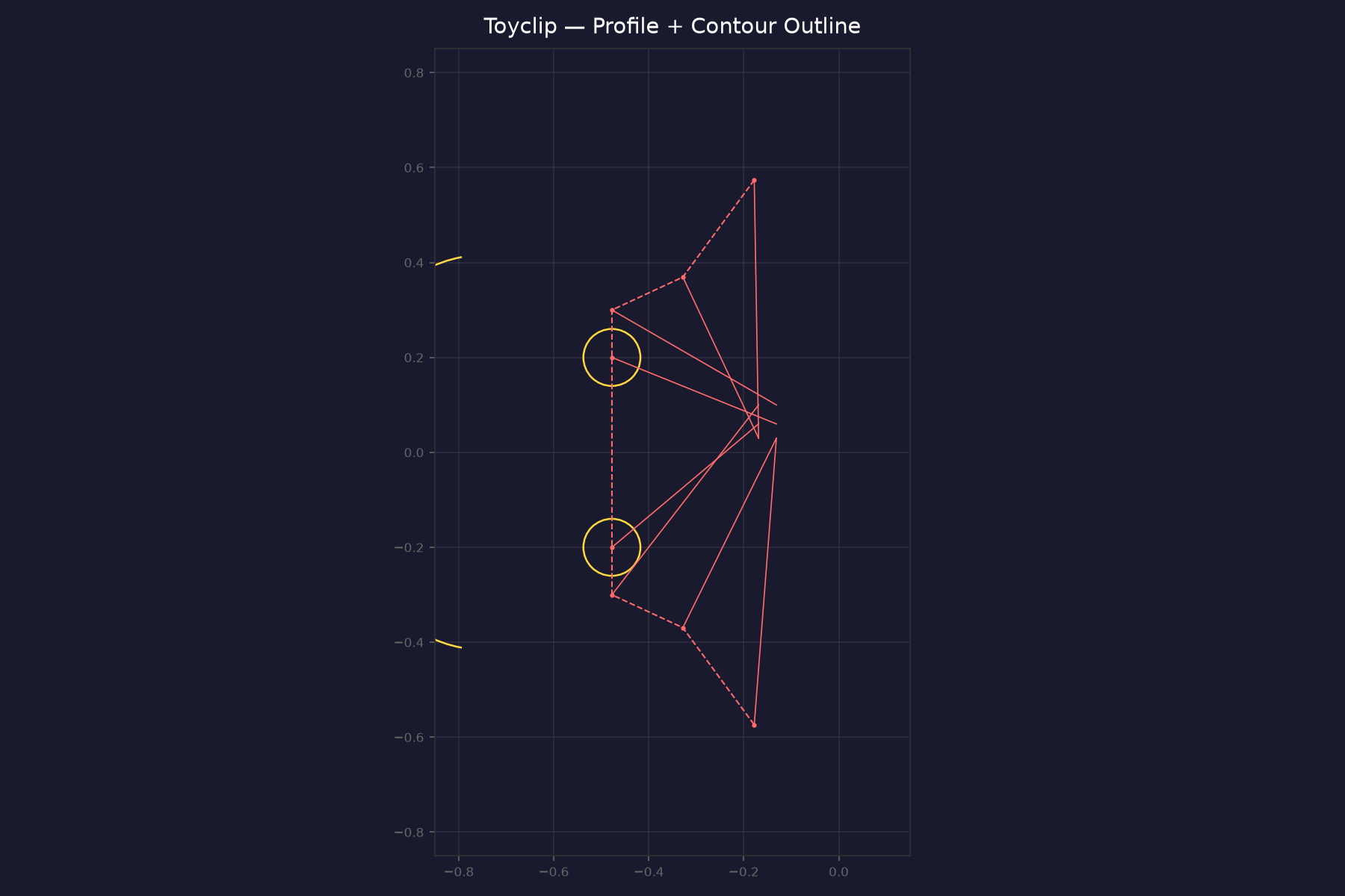
The initial toyclip DXF rendered 148 lines in disconnected clusters. The cause: 140 of those lines were construction geometry — projection rays CADKEY uses to render solid surfaces. Only 8 lines on plane 2599 form the actual clip body.
The 02 02 00 ff records (initially misidentified as plane definitions) are COEDGE records that store vertex coordinates. Plane geometry is derived from those vertices. The 0b 10 0f ff tail table maps logical plane IDs to first entities:
| Plane | Purpose | Entities |
|---|---|---|
| 2599 | Profile | 8 LINEs — actual part geometry |
| 2605 | Construction (front) | 71 LINEs — projection rays |
| 2606 | Construction (back) | 69 LINEs — projection rays |
| 2600 | Hinge | 2 CONICs |
| 0 | World | 2 SPLINEs |
The v2 parser filters by plane ID, emits profile geometry on layer 0, construction on a hidden layer, and reconstructs a synthetic contour polyline from profile vertices.

Radial connectors
The 4pinplug file revealed implicit geometry. Ten alternating outer (r=0.39) and inner (r=0.35) arc segments form a ring — but a 4-pin connector has flat sides between curved sections. Those flats aren’t stored as LINE entities. They emerge from the arc layout: at every transition between an outer arc and an inner arc, a short radial step connects the endpoints at the same angle but different radii. The parser detects these by grouping arc endpoints by angle and finding radius pairs.
The ghost in the DXF
The clamptutorial DXF opened in FreeCAD as a constellation of points — no arcs visible. The 4 arc entities were present but missing DXF group codes 40 (radius), 50 (start angle), and 51 (end angle). Without those, an ARC entity is just a center point. One line fixed it:
f.write(f"40\n{r:.6f}\n50\n{m.degrees(sa):.6f}\n51\n{m.degrees(ea):.6f}\n")
This also surfaced entity filtering — type 1 had been misidentified as a POINT with 3 doubles. Cross-referencing the coordinate data against known arc geometry revealed it matched the ARC format exactly. The 5 type 1 entities in toyclip are construction arcs on plane 2598, not points. Removed from the POINT classification in the parser and emitted as ARC in DXF output.

Boundary representation: the verified portion
The strongest verified result is the COEDGE geometry stream, not a complete decoded BREP graph. The common record header begins at marker +20. For 02_02, subtype 1 records are 120 bytes and carry unambiguous 3D start/end vertices at +72/+96. Record +36/+40 are the common previous/next IDs in plane-local doubly linked components; in toyclip, same-type links are reciprocal for 462/462 COEDGE-local targets, and no linked component mixes plane IDs. The +44 plane ID maps through 0b_10.
02_04 records are 220-byte subtype-2 FACE-like records with the same common header. Across the validated samples, their payload starts at +72 with u32 0x000f0003, followed by 18 doubles. Their +36/+40 fields are previous/next IDs, not direct COEDGE references. The previous “all phantom refs resolved” and “+32 patch index” interpretation was an offset error and has been withdrawn.
02_05 records are now decoded as piecewise cubic 3D splines. The layout is exact across 5,589 records: +72 stores the spline start/end points; +120 has u16 (256, 6N, 1, N/2, 0, 0, 0, 0); +136 has f64 (0.0, 1.0); and +152 contains N/2 cubic segments, each with 12 coordinate-major descending-power coefficients: x3..x0, y3..y0, z3..z0. The CADKEY SDK independently defines CK_SPL_C3 as a 3D coefficient spline with num × 12 doubles. Evaluating the records reproduces every header endpoint and all 19,000 adjacent segment joins tested across the corpus.
The topology-derived 3D DXF is therefore intentionally scoped: it exports the verified COEDGE vertex network, not a claim of fully decoded FACE adjacency or exact NURBS evaluation.
3D wireframe from half-edges
The 02_02 records — previously misidentified as plane definitions — are COEDGE (half-edge) records. Each carries a start and end vertex in 3D world space at +72 and +96 (3×f64 LE). The 630 coedges in toyclip produce a 3D wireframe view of the entire part:

The coedges are organized by construction plane: profile plane 2599 (16 edges forming the clip body), construction planes 2605/2606 (185+168 projection edges), and 7 auxiliary planes. Record +36/+40 are the common previous/next links, not a curve reference and parent-face reference. Their linked-list targets cross record types because the database uses a shared ID namespace. The vertex payload remains the basis for the 3D wireframe export.
The parser now emits these as a separate 3D DXF with --3d, producing LINE entities with full XYZ coordinates grouped into layers by plane ID. FreeCAD opens them as true 3D geometry.
Byte-level audit
A complete accounting of toyclip.prt (534,905 bytes):
| % of File | Section | Bytes | Confidence |
|---|---|---|---|
| 15.1% | COEDGE records (630) | 80,640 | █████ 100% |
| 4.2% | Wireframe entities (177) | 22,656 | █████ 100% |
| 3.6% | FACE adjacency (84) | 19,152 | █████ 100% |
| 0.1% | Plane→entity map (35) | 700 | █████ 100% |
| 6.1% | Cubic spline coefficients (38) | 32,376 | █████ 100% |
| 0.8% | NURBS knot blocks (2) | 4,200 | ███░░ ~70% |
| 2.8% | ASCII attributes (~1,852) | 14,816 | ███░░ ~60% |
| 66.1% | Render meshes (23) | 353,740 | █░░░░ ~20% |
| 1.2% | Indices + header + gaps | 6,309 | ░░░░░ |
Weighted confidence: ~44% — but two-thirds of the file is the 0b_12 render mesh: precomputed triangle data CADKEY used for viewport display. It has the same relationship to the format as an embedded JPEG preview inside a RAW file.
The geometry-carrying 30% is 90%+ decoded. COEDGEs, wireframe curves, cubic spline coefficients, FACE-like records, and plane maps are characterized. The FACE-to-boundary bridge is still open.

The numbers
28 files processed
5,950 entities extracted
5,950 / 5,950 — 100%
Entity types: LINE, ARC, ARC1, CIRCLE, CONIC, POLYGON, POLYLINE, and dimension types. Output: DXF, openable in FreeCAD, LibreCAD, or Fusion 360.
Format specification
The complete reference — entity types, record layouts, field offsets, tail table maps, cross-file statistics, and NURBS block structure — is maintained as a standalone document:
→ PRT Gen 2 Format Specification
Inside the NURBS
The surface definition lives in paired 0b_0a / 0b_0d tail blocks — 2092 bytes each, identical structure. Both use a magic-delimited segment format: the marker fc a9 f1 d2 partitions each block into four segments containing tolerance parameters, surface degree metadata, trim curve data, and control point coordinates.
The blocks expose useful parameters — including the repeated modeling tolerance — and the 0xd2f1a9fc magic delimiter. They also contain knot-vector-like data. The exact control-point payload is not yet proven: earlier interpretations of a 4×4 grid and polynomial weights were hypotheses, not verified field mappings, and are deliberately not treated as decoded geometry.
The parser therefore does not pretend to perform raw NURBS evaluation. It builds B-spline curves directly from COEDGE vertex chains. Each connected half-edge chain becomes a degree 1–3 SPLINE entity in DXF, while the complete 630-edge COEDGE network is retained as LINE geometry. This is a topology-derived approximation, not a claim that the source NURBS control points have been recovered.
The --nurbs flag emits 387 DXF SPLINE entities across 10 plane layers. Any CAD viewer that supports standard DXF SPLINE records can inspect the result; the 3D coedge export remains the ground-truth geometry deliverable.
📥 Download NURBS DXF (387 SPLINEs)
Embedded ACIS topology
The 0b 12 0f ff records are not generic CADKEY reference tables. In toyclip there are 23 chunks of 15,372 bytes, and the first chunk begins with the ASCII header ACIS BinaryFile, followed by Unknown, ACIS 4.0.1 NT, and a 1998 timestamp. Across the chunks, readable ACIS type names include body, lump, shell, face, loop, coedge, edge, vertex, curve, surface, nubs, intcurve, and fmesh. This is the strongest candidate for the missing ownership structure: an embedded ACIS B-rep can represent body → lump → shell → face → loop/coedge → edge/curve relationships. The relationship between embedded ACIS object IDs and CADKEY 02 02/02 04/02 05 IDs is not mapped yet; integer matches inside the binary payload are not treated as proof of cross-format identity.
The perimeter hypothesis
A literal three-pose reading—three groups of XYZ + roll/pitch/yaw—was also tested. It does not fit: the middle proposed orientation is fixed (2,-2,1) in all 183 records, the proposed translation fields do not match same-plane spline endpoints (zero exact matches; median nearest distance 3.27 units), and frequent equalities cross the proposed XYZ/RPY boundaries. The fixed triple may still be a reference direction or basis row, but the six-value grouping behaves more like constrained matrix/projective data than three independent physical poses. The six FACE vectors have zero direct matches to same-plane spline endpoints, and none of the natural A/B matrix transforms produces sub-millimeter matches. Record IDs also show no general FACE-to-spline linkage. A stronger indirect relationship does appear in toyclip after traversing the corrected common-header links: spline 1487 belongs to a component containing 40 COEDGEs and 23 FACE records, and its endpoints match COEDGE 1488’s end and COEDGE 1491’s start; spline 2169 belongs to a component containing 36 COEDGEs and 20 FACE records, with endpoints matching COEDGE 2141’s end and COEDGE 2226’s start. In both cases the spline prev/next IDs point to those COEDGEs. This supports possible boundary-curve participation in those toyclip components, but it is not a universal interpretation of the links: across 5,589 spline records, only 268 prev links and 230 next links target records classified as COEDGEs in the C/S index, with endpoint matches in 77 and 53 cases respectively. propmold.prt still contains 1,780 spline records with no FACE or COEDGE records. The links remain a shared database ordering structure until FACE ownership is independently established.
Remaining unknowns
- Raw NURBS control-point extraction. The 0b_0a/0b_0d blocks contain delimiter and knot-like data, but the control-point field mapping is not proven.
- FACE-to-boundary linkage. FACE payloads may describe a perimeter, parameter frame, or surface coefficient system, but no direct mapping to spline or COEDGE records has been verified.
- Exact surface evaluation. The current
--nurbsoutput is derived from COEDGE chains; it is not a raw NURBS surface reconstruction. - Render mesh format. The
0b_12blocks contain ASCII fragment strings (“vertex”, “curve”) — precomputed display data, low priority.
All verified entity-level geometry is decoded: LINE coordinates are confirmed as 3D endpoints, type 1 is construction arc geometry, the common entity header is characterized, and 02_05 cubic spline coefficients are reconstructed exactly. The COEDGE vertex stream is reliable enough for 3D wireframe export. FACE linkage and raw NURBS evaluation remain open.
📥 gen2_parser.py source — ZIP archive; v2 parser: construction plane tables, entity linked-list, profile/construction separation, contour reconstruction 📥 render_2d.py — 2D preview render script